Word count: 2218. Estimated reading time: 11 minutes.
- Summary:
- A year-long project to automate the blinds in a house using 3D printing and motorization has finally been completed. The original IKEA Fridans blind was chosen due to its low cost and simplicity, with the goal of creating a fully automated system that would be affordable for a large number of windows. The project involved designing and 3D printing custom parts to replace the manual stick at the side of the blind, as well as selecting and integrating a motor and driver board that would meet specific power requirements. The final result is a functional and efficient motorized blind system that can be controlled using an ESP32 microcontroller.
Sunday 22 December 2024: 17:26.
- Summary:
- A year-long project to automate the blinds in a house using 3D printing and motorization has finally been completed. The original IKEA Fridans blind was chosen due to its low cost and simplicity, with the goal of creating a fully automated system that would be affordable for a large number of windows. The project involved designing and 3D printing custom parts to replace the manual stick at the side of the blind, as well as selecting and integrating a motor and driver board that would meet specific power requirements. The final result is a functional and efficient motorized blind system that can be controlled using an ESP32 microcontroller.
3D printing extensions to an IKEA Fridans blind to avoid the expense of IKEA Fytur blinds.
… which I kept putting off as it would need a lot of work to type it up. Here is finally that post!
This is probably one of the longest running projects I had of them all. It ran for over a year. What I’m about to write out removes all the blind alleys, the ideas which didn’t work out, all not helped by having to usually wait two months for new parts from Aliexpress to arrive in the post. Before you knew it, it was a year later. Mad.
Automating blackout blinds cheaply
One of the signature features in any automated house is motorised blinds which automatically open and close themselves according to sunrise and sunset. They have historcially been very expensive, typically €500 or more per window, so only very rich people would fit them. IKEA shook up this market with battery powered radio controlled blinds called ‘Fytur’ for under €120-160 per blind. These are great and all, but if you have nearly thirty windows, it’s still thousands of euro.
IKEA also sell the Fridans blackout blind which is operated using a stick at its side. This is very considerably cheaper at €22-28 per blind. Their build quality isn’t great, but for the price they’re a good base for a DIY automation which replaces the manual stick at the side with a motor.
This is hardly my own idea. https://www.yeggi.com/q/ikea+fridans/ will show you thousands of 3d printables related to IKEA Fridans blinds. Most involve replacing this part:

This is the manual stick at the side. You push and pull on it to turn the blind – internally there is a cord with plastic beads which can be reexposed if desired by cutting off the plastic handle, and have a motor push and pull on the cord directly. We’ll be going a bit further – 3D printing a complete replacement for the above with identical dimensions, just minus the handle.
I reckon that all in you can do one of these fully automated blinds for under €40 inc VAT for the 200 cm blind, and under €30 inc VAT for smaller blinds. This excludes the 5v power supply only (often an old USB phone charger will do for that), that’s the price for everything else. This turns thousands of euro of cost for me if we chose the IKEA Fytur solution into hundreds of euro instead, and with very little manual work (apart from all the work done to come up with what I’m about to describe now).
Choosing the motor
If you go through the many, many IKEA Fridan blind automation projects, you will find a legion of motor solutions. Some people use 12v, some 9v, some 5v for power. Various microcontroller and driver boards are used, all with different voltages and currents. In my case, I had very specific needs:
- The entire thing had to work within the power budget of an Olimex ESP32-PoE board running off PoE. That as my notes described gives you up to four watts off PoE before it browns out, which includes everything on the board or hanging off it. That means max three watts for peripherals.
- There is a much better v2 Olimex PoE board now for nearly the same price as the original which has a 12v power tap. Mine, being the older ones, has a max 5v supply. So the motor needed to run off 5v, and never consume more watts than the board has spare.
- My longest blind is 1.8 metres in the kitchen. It needs enough torque to turn that from fully extended.
Those requirements it turns out reduce thousands of options down to approximately two. The first I alighted upon is the 28BYJ-48 unipolar motor hacked into a bipolar configuration. As a unipolar motor, its native voltage is 5v approx 0.1 watts in power. Typical torque is 0.3 kgf.cm with stall torque at 0.6 kgf.cm. Hacking it into bipolar doubles the active windings, so you now might get 0.2 watts of power, 0.6 kgf.cm of torque and 1.2 kgf.cm of stall torque. Obviously the motor was not designed for both windings to be concurrently active so it will get hot quickly. The 28BYJ-48 is however cheap for the spec, about €2.50 delivered which includes a ULN2003 driver board.
I then fortunately landed on something not needing every motor housing to be opened and hand modified: https://github.com/AndBu/YAIFM and my customisations of his project can be found at https://github.com/ned14/YAIFM. This uses a GA12-N20 bipolar motor with integrated encoder. These vary in power and spec despite using the same model name, so you need to choose very carefully to get one with the right combination of torque and power consumption when stalled.
The one I chose off Aliexpress claimed these specs:
| Motor Specification Table | ||||||||
|---|---|---|---|---|---|---|---|---|
| Model | GA12-N20 (GA12-B1215) | Rated Voltage | DC12V | |||||
| Type | DC Brushed Geared Motor | Test Voltage | DC6V | |||||
| No-Load | Rated Load | Stall | Reduction Ratio | |||||
| Speed (RPM) | Current (A) | Speed (RPM) | Torque (kgf.cm) | Current (A) | Power (W) | Torque (kgf.cm) | Current (A) | |
| 15 | 0.02 | 12 | 1.25 | 0.05 | 0.3 | 8 | 0.35 | 1000 |
| 25 | 0.02 | 20 | 0.8 | 0.04 | 0.24 | 4.9 | 0.29 | 298 |
| 30 | 0.02 | 24 | 0.85 | 0.04 | 0.24 | 5.85 | 0.31 | 298 |
| 40 | 0.02 | 32 | 0.95 | 0.04 | 0.3 | 6.8 | 0.35 | 298 |
| 50 | 0.02 | 40 | 0.95 | 0.05 | 0.3 | 7.75 | 0.35 | 298 |
| 60 | 0.02 | 48 | 0.8 | 0.05 | 0.3 | 7.3 | 0.35 | 250 |
| 80 | 0.02 | 56 | 0.34 | 0.05 | 0.3 | 4 | 0.35 | 200 |
| 100 | 0.02 | 80 | 0.48 | 0.05 | 0.3 | 3.4 | 0.35 | 200 |
| 120 | 0.02 | 96 | 0.23 | 0.04 | 0.24 | 1.8 | 0.3 | 150 |
| 150 | 0.02 | 160 | 0.27 | 0.05 | 0.3 | 2.15 | 0.36 | 100 |
| 200 | 0.02 | 200 | 0.28 | 0.06 | 0.36 | 2.3 | 0.37 | 100 |
| 300 | 0.02 | 240 | 0.2 | 0.05 | 0.3 | 1.6 | 0.37 | 50 |
| 400 | 0.02 | 320 | 0.24 | 0.05 | 0.3 | 1.8 | 0.37 | 50 |
| 500 | 0.02 | 400 | 0.15 | 0.05 | 0.3 | 1.2 | 0.35 | 30 |
| 600 | 0.02 | 480 | 0.16 | 0.05 | 0.3 | 1.3 | 0.37 | 30 |
| 700 | 0.02 | 560 | 0.17 | 0.06 | 0.36 | 1.4 | 0.37 | 30 |
| 800 | 0.02 | 640 | 0.18 | 0.06 | 0.36 | 1.5 | 0.38 | 20 |
| 1000 | 0.02 | 800 | 0.42 | 0.1 | 0.42 | 1.6 | 0.39 | 20 |
| 1200 | 0.02 | 960 | 0.1 | 0.05 | 0.3 | 0.5 | 0.33 | 10 |
| 1500 | 0.02 | 1200 | 0.07 | 0.04 | 0.24 | 0.55 | 0.33 | 10 |
| 2000 | 0.02 | 1600 | 0.08 | 0.05 | 0.3 | 0.6 | 0.35 | 10 |
Again, I stress that the above table is what the Aliexpress claims for my specific GA12-N20 motor. Other GA12-N20 motors will have very different tables.
The 50 rpm model highlighted (which has the maximum stall torque of all models) at 6v uses 0.3 watts, typical torque is 0.95 kgf.cm with stall torque at 7.75 kgf.cm. Max amps at stall is 0.35 amps (2.1 watts, within my power budget). The motor plus a DRV8833 driver for it is about €6 delivered, so nearly double the cost of the previous option. However, it delivers (i) 58% more turning torque (ii) 650% more stall torque and (iii) I’m fairly sure the chances of coil burnout would be much lower with this choice.
Not all GA12-N20 motors come with a rotary encoder, which you will need as it counts how many turns the motor does, which we will then use in software to wind the blind to exact positions. A six wire cable is usually supplied, and its pinout means:
- Red: Motor forwards.
- White: Motor backwards.
- Blue: Common ground.
- Black: 3.3v - 5v power supply for the encoder.
- Green: Encoder A phase.
- Yellow: Encoder B phase.
You still need a driver for the motor which is the DRV8833 dual H-Bridge. It works the same as any other H-Bridge motor driver, you set a PWM either forwards or backwards as desired and the motor goes. The DRV8833 rather usefully will take a TTL input and output 5v, so you don’t need a level shifter. Just feed its Vin with 5v, also raise its EEP input to 5v, and voila it all just works with the PWM inputs straight off the ESP32 using the 5v supply off the Olimex board.
ESPHome’s rotary encoder driver will read the A and B encoder pulses. Make SURE you connect 3.3v as its power supply, otherwise the encoder outputs will have too much voltage for the ESP32.
Anyway here it is in action, being driven by ESPHome:
Blind motor driven by a DRV8833 using the 5v supply from PoE
I did lots of testing to try to make the solution brown out, but I failed. I found the following power consumptions off PoE:
- No load, just turning: 105 mW.
- Max load, PWM at 50%: 263 mW.
- Max load, PWM at 100%: 315 mW.
These seemed surprisingly low, so I redid them off USB power:
- No load, just turning: 166 mW.
- Max load, PWM at 100%: 600 mW.
The cause of the disparity is that the PoE power conversion circuitry is especially inefficient at low loads, but gets more efficient as load goes up. The effect is to ‘hide’ some of the power consumption of the motor. Obviously, I only care about peak PoE consumption, so 315 mW looks great.
What about stall current? Well, the thing has so much torque you need two hands to stop it turning. I have my software detect jams within 160 milliseconds and cut the power. Perhaps that meant I never saw the stall current for long enough to measure it, but equally the Aliexpress listing could just be increasing all power claims by 50-100% as they sometimes do. 350 mA at 6v should be ~292 mA at 5v, which is 1,460 mW. I didn’t measure even half that including when I stalled the motor.
There is another possibility: the DRV8833 is mounted on a board called ‘HW-627’. There is very little information about that board that I (or anybody else) can find, but it may well configure the overload protection in the DRV8833 to cut off the power in the case of stall at some fairly low limit. I can say I see several capacitors and resistors on the board, so it’s entirely possible they set a lower overload limit.
Making the blind stop turning when open
The original YAIFM project used either a mechanical switch to detect blind fully open, or you had to program it manually with a count every time there is a power loss. The switch is visually intrusive, and manually setting a count for each of thirty blinds isn’t practical. So I wondered if we could have the ESP32 detect when the blind stops turning, and choose that as the new base point for winding the blind down and up until the next power loss?
The first thing I’d need to fix is that the Fridans blinds have nothing to stop them keeping turning once fully open, because the blind bottom will happily wrap round the upper housing. To solve this, I designed so 3D printed inserts to extend the width of the bottom of the blind. This also doubles as an ‘anti-fray’ shield, because the bottom corners of those Fridans blinds are notorious for getting scruffy very quickly:
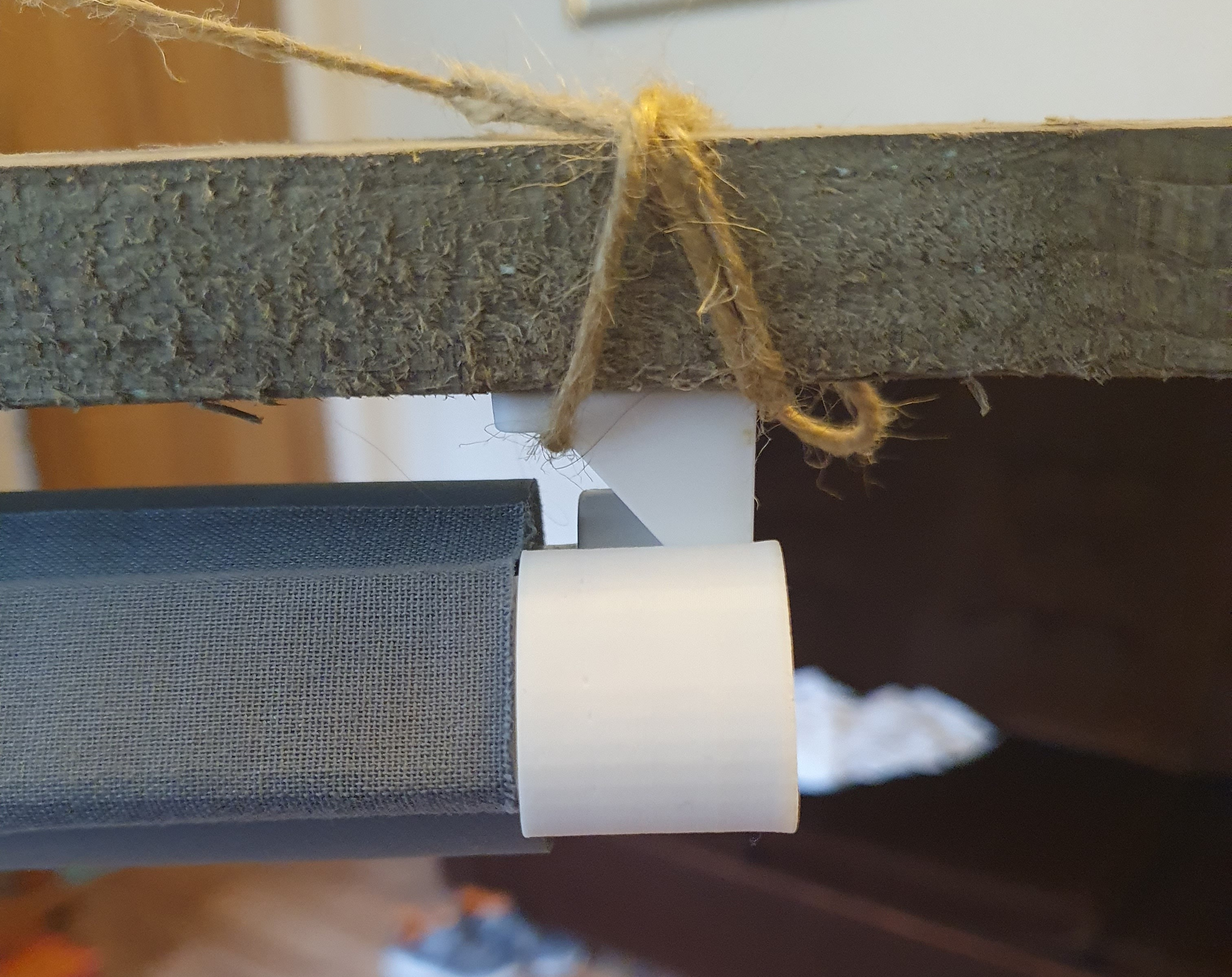
One side of the 3D printed width extension for the Fridan blind. The existing weighted plastic bar in the blind's bottom inserts into the 3D printed component to hold it in. A pleasant looking oval shaped external 'knob' then protrudes in a way to ensure it will prevent the blind passing through once fully open.
Strengthening the 3D prints
The next problem I found is that the plastic just can’t take the torque that this motor puts out. I know this from manually putting load onto the motor by hand, it did not take long before the D-shaped hole for the motor in the printed plastic went circular, and now the blind spool wouldn’t turn. This clearly would need to be fixed.
After a great deal of searching I finally found some metal cogs off Aliexpress which fit the motor’s D shaft (I won’t bore you with the cogs tried and found to not fit, that wasted many months. I really wish listings described measurements the same way!). What you’d need is the ‘9 Teeth D Type’ which has an outer diameter of 8 mm and is 7.4 mm long. The key measurement is between the flat part of the D hole rising perpendicularly to the topmost of the rounded part of the D hole – that needs to be 2.4 mm if you want it loose, 2.3 mm if you want it tight. For some reason, these can cost a lot or not at all depending on the listing, so for reference mine cost €0.82 inc VAT each delivered.
I then remeshed the original YAIFM blind spool to take the metal cog instead of the D-shaped shaft of the motor. I also thickened up some of the plastic, as I reckoned it would be getting repeated stress.
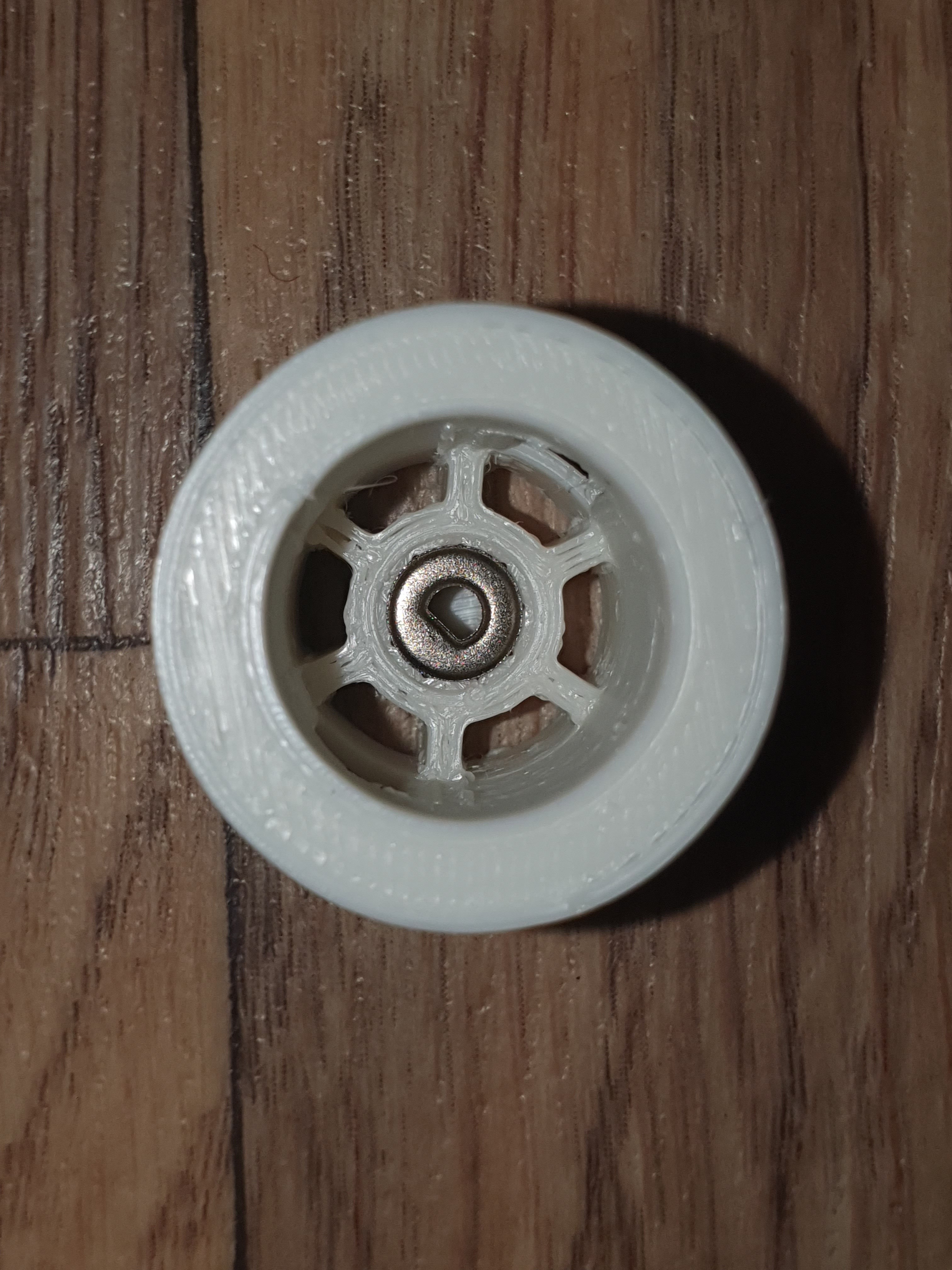
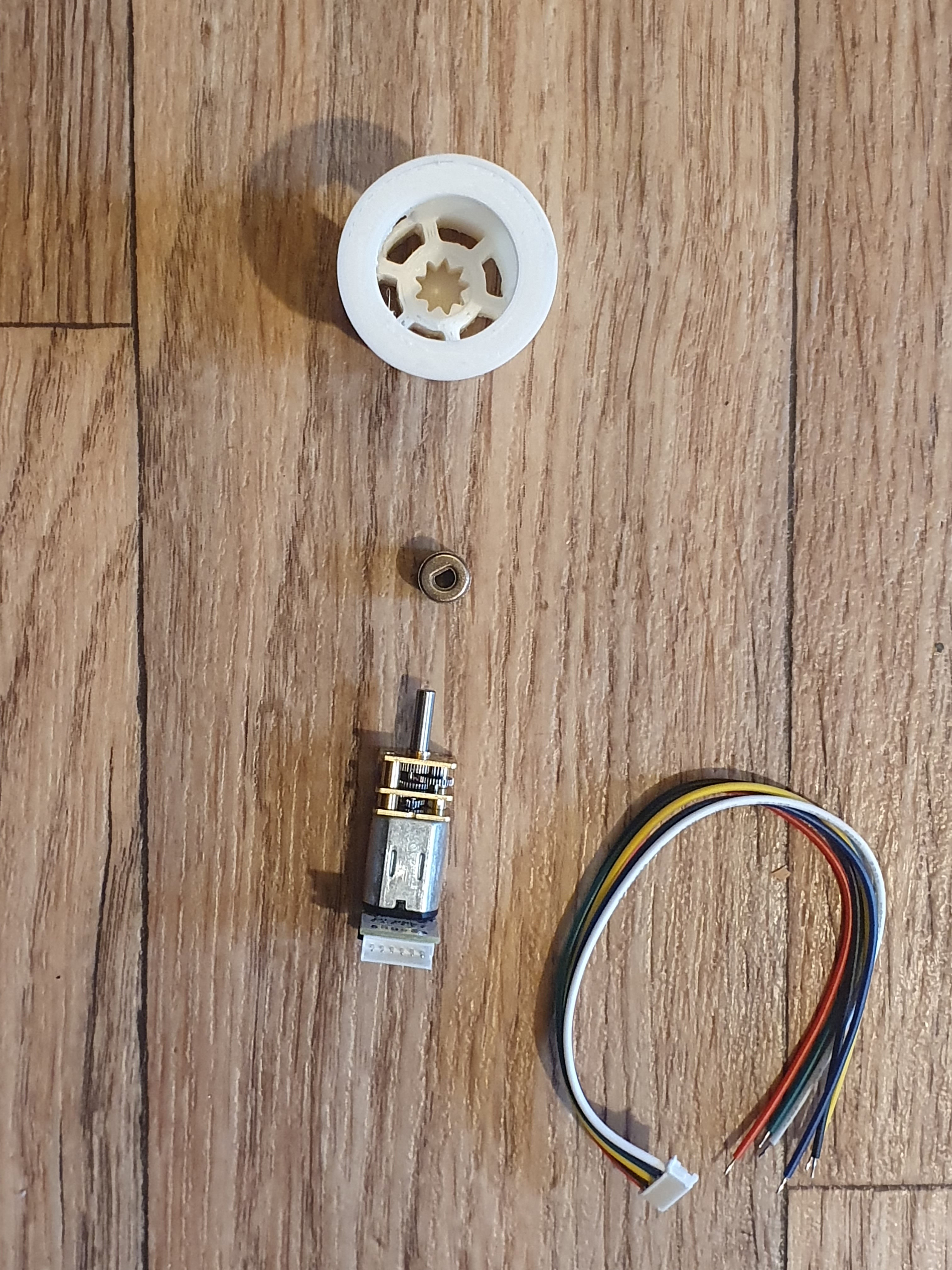
Above is the 3D printed blind spool with cog shaped hole, the metal cog, the GA12-N20 motor with rotary encoder, and its cable. I added two metal washers between the metal cog and the motor to ensure horizontal force landed mainly on the motor housing, not on the motor shaft. You do still get the weight of the blind bearing down on the motor shaft, but it’s probably good for a few years.
Putting it all together:
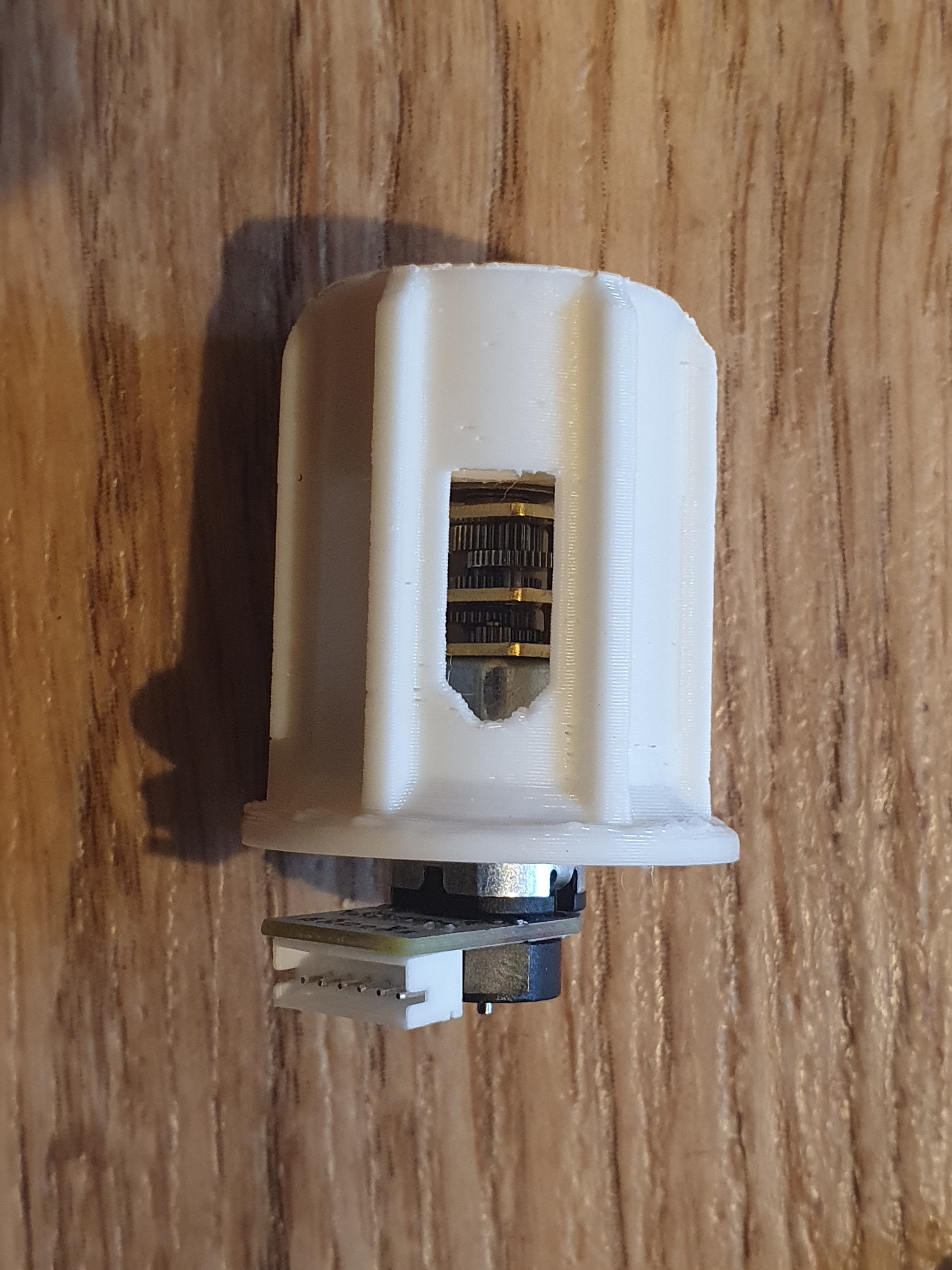
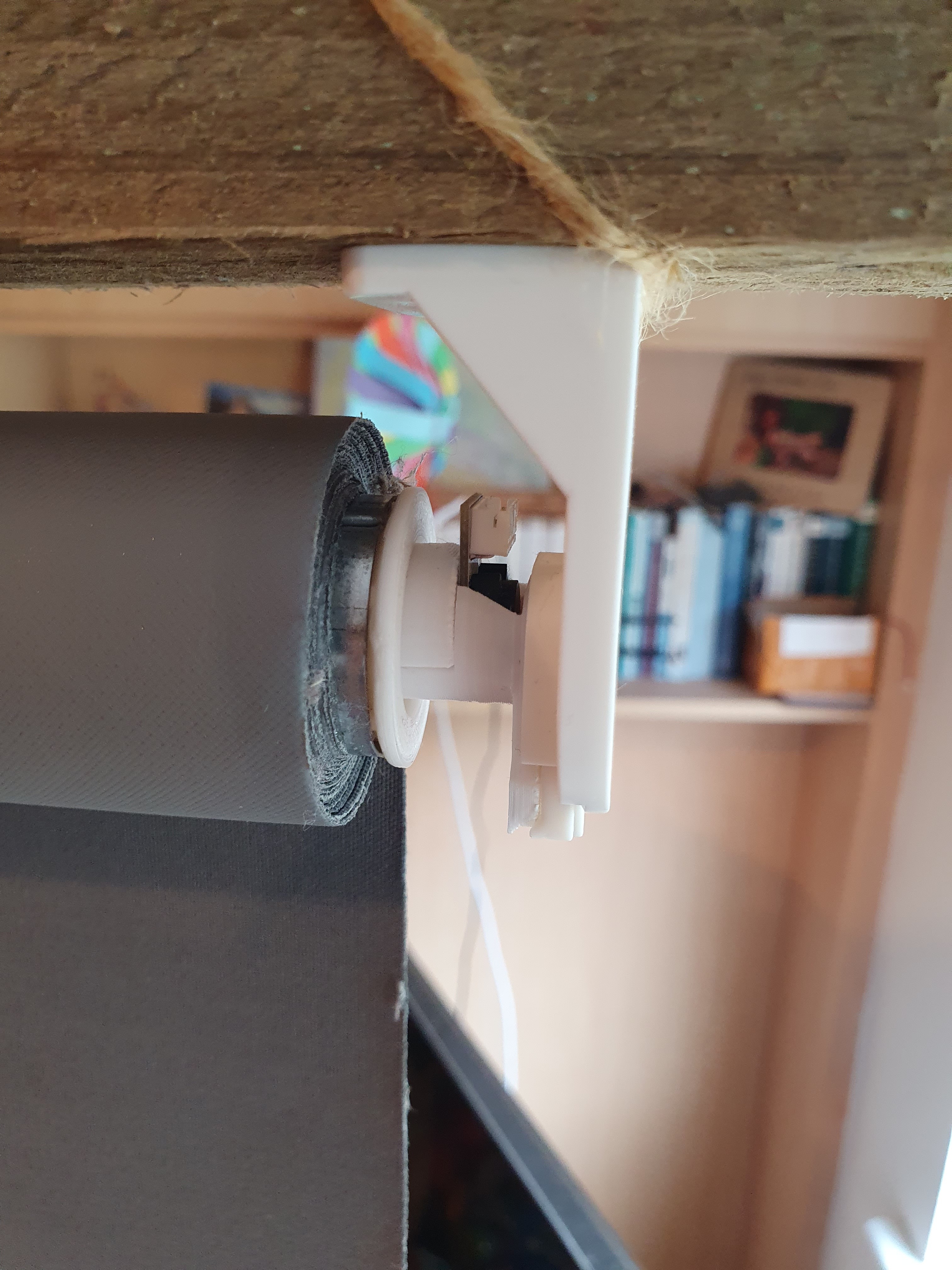
And that’s pretty much it! The great thing about this particular IKEA Fridans blind customisation is that the 3D printed parts exactly replace the originals in dimensions, so as you can see in the rightmost picture above the blind fits exactly identically to before except you now have a wiring connector. From that you take your cable to your MCU.
The motorised blind in action
Completed blind being automated from ESPHome exclusively using the 5v supply from PoE for power
This won’t have looked like a particularly long post, and it’s not. Where most of the real work went in was preparing all the materials for upload, which meant cleaning them up, writing a single set of coherent truth from all the notes, and then writing it effectively three times once for Thingiverse, once for Github, and once for here. Here are the links:
Thanks for reading and enjoy!
| Go to previous entry | Go to next entry | Go back to the archive index | Go back to the latest entries |