Word count: 3382. Estimated reading time: 16 minutes.
- Summary:
- The BTS7960 H-bridge is being used to drive a ventilation boost fan, which has been successfully tested and found to work well with an ESP32 controller. The fan can be controlled at any speed by adjusting the PWM output from the ESP32. However, there are still some issues to resolve, such as detecting air flow direction and dynamically adjusting the fan reverse to keep air flow stopped.
Saturday 5 October 2024: 11:46.
- Summary:
- The BTS7960 H-bridge is being used to drive a ventilation boost fan, which has been successfully tested and found to work well with an ESP32 controller. The fan can be controlled at any speed by adjusting the PWM output from the ESP32. However, there are still some issues to resolve, such as detecting air flow direction and dynamically adjusting the fan reverse to keep air flow stopped.
Anyway here’s hoping that by this time next month we’ll be out of structural engineering. Three months for SE is a long time.
As we all sit around waiting, I have been pushing onwards with the future house projects. Last post I mentioned:
Implementing the ventilation boost fan per inlet and outlet in the house.
3D printing extensions to an IKEA Fridans blind to avoid the expense of IKEA Fytur blinds.
Dimming RGBW LED strips with my ‘new’ IRF540N MOSFET boards.
I haven’t got to item (3), but I’ve made significant progress with (1) and (2). (1) is what I’ll be writing about today.
Ventilation boost fans
Last post I said:
I shall be testing a €4 inc VAT driver based on what Aliexpress claims is a BTS7960 H-bridge. It claims it can handle 43 amps, the reviews are clear it cannot, but it should handle the max 3 amps we’ll ever demand from it. The BTS7960 can take a max 30v, so I’m a little concerned that back EMF from the 24v bilge pump fan might spike over that. However it would seem that these bilge pumps respond very well to lower voltages, they turn well at 5v and have more than plenty flow in my opinion at 12v (and at 24v, they’re insane) so chances are very high I’ll run them at 12v and make everything easier on myself.
And here it is wired up:
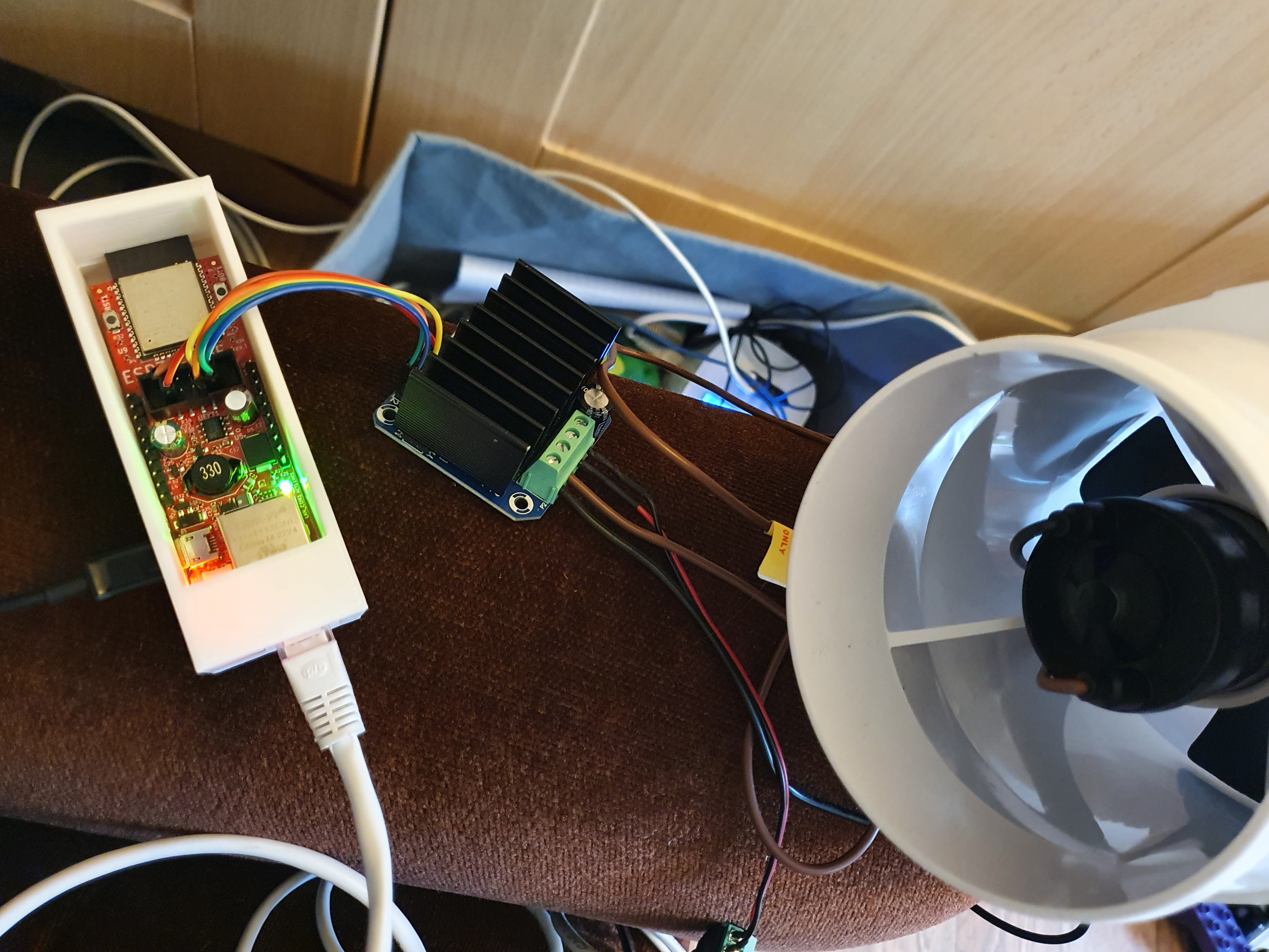
The BTS7960 H-bridge is by far the cheapest ‘not small’ motor driver on Aliexpress. I had been a little worried about it, but having tested it myself and watched plenty of YouTube videos of other people testing it (including to destruction), I’m feeling much happier with it. The BTS7960 ICs themselves (assuming they aren’t fake clones) claim a max 43 amps, but they’ll throw out an enormous amount of heat for that and besides the cheap module these are mounted on doesn’t have thick enough traces to handle such current. YouTube reviews reckon the safe maximum without active cooling is about 15 amps, and moving the heatsink from the ‘wrong’ side to the front also helps.
There isn’t much to the ESPHome scripting for this – you put a PWM onto the forward and backwards pins, and a digital output onto the forwards and backwards enable. Enabling both backwards and forwards shorts the windings, which equals braking now as the back EMF from the motor stops the turn quicker than preventing the back EMF flowing. The BTS7960 is happy with 3.3v TTL and at the currents that the ESP32 outputs, so it ‘just works’:
Ventilation fan driven by a BTS7960 and an external 12v DC power supply
The first thing you may notice in the video is coil whine – for some reason I don’t remember now, I had configured the PWM for these to 3662 Hz so unsurprisingly, there is a clear 3662 Hz tone in the video. I think I might have done that to reduce the impact of voltage spikes from back EMF on the electronics, but if I’m now running at 12v which I think I am (as you can see, they still go like the clappers despite being 24v motors), then something much higher frequency would make sense. The ESP32 has a 80 Mhz base frequency for its PWM, so the obvious choice would be 625 kHz to give 128 steps. However the datasheet for the BTS7960 says 25 kHz is the maximum, so 2048 or 4096 steps seem like reasonable choices and nobody will be hearing 20 kHz whine.
The second thing you may notice if you have a HDR display is that the above video ‘glows’ brightly compared to the rest of the page. This is because it is in HDR10+! What won’t be so obvious is that it’s the first ever AV1 encoded video on this website, and I encoded it at 1080p Full HD in ten bit HDR with stereo AAC audio with a capped bitrate of 500 Kb/sec. That entire minute long video is only 3.8 Mb long! Two hours of it would be 456 Mb.
I think you’ll agree that it came out very well for such a low bitrate, so I expect to be mounting all future videos directly on this website instead of having YouTube host them. I only have seven videos on YouTube, so there’s even an argument of converting the lot down to be direct. I had only ever mounted two videos directly to this site before, both reduced severely in resolution to keep the file small, but if AV1 can encode 1080p Full HD in HDR10+ at that kind of quality for that low file size I think that’s the future. What I’m still wrapping my head around a little is that twenty five years ago, ninety minute movies came in a 700 Mb file to fit on a CD. For that you might have gotten 720 x 340 resolution encoded in MPEG-4 with MP3 encoded audio. Here we are in 2024 with 8.5x more resolution and Rec.2020 colour gamut in half the bitrate. It’s impressive.
My phone which took the video remains the venerable Samsung Galaxy S10 from 2019. I’ve never owned a phone past two years until this phone, and here it is still going strong into its fifth year (batteries clearly took a huge leap forwards around then). Mine runs Android 11, mainly because I keep thinking it isn’t worth upgrading to Android 12 as surely at some point ‘soon’ I’ll be replacing it. Amazingly, you need Android 14 to take photos which retain the HDR information in the file – despite that as early as Android 10 you could happily take HDR video if the hardware was capable. It’s one of those things you’d have thought very easy to implement much sooner, but apparently not.
Anyway I think that’s the first half of the ventilation boost fan problem solved – it goes forwards and backwards at any speed you like under ESP32 control. There is more though: how do we decide by how much to reverse the fan to stop the flow i.e. how do we detect air flow direction and dynamically adjust the fan reverse to keep air flow stopped?
Detecting ventilation air flow (cheaply!)
I’ve sized the ventilation ducts in the house for a linear pressure loss of 0.5 - 1 Pa per metre, so if we want to cut off air in one part of the house (by turning its boost fans into reverse) to boost heating or cooling in another part of the house (by turning its boost fans forwards), we have some slack in the ducts to drive boosted flow in that direction. The Zehnder ComfoAir Q600 data sheet says it should not have more than 200 Pa pressure at the unit for a long service life, so we will need to balance the speed of the fans to ensure no excessive loads anywhere in the system. For this, ideally speaking, you’d fit air velocity meters at every ventilation inlet and outlet.
The FS3000 sensor is exactly what one would prefer – it has two models, one can measure up to 7.23 metres/sec and the other up to 15 metres/sec. The worst case air velocity in this system is the 180 mm diameter connection at the MVHR unit which is 6.52 metres/sec, so the first model would be the right one. Unfortunately, the FS3000 sensor it is expensive – cheapest I can find it is €55 inc VAT delivered each. I have seven boosted stale air outlets and eight boosted fresh air inlets, so that would cost me €825 inc VAT which is a bit much. Can I do it cheaper?
A Mass Air Flow Sensor like cars use are much cheaper, but as they work by measuring the resistance of a heated wire in the airflow, they are non-linear temperature sensitive and my fresh air outlets will have varying temperatures, so that won’t work. What I really need is something solid state, and temperature insensitive.
I had a few spare BME280 temp + press + humidity sensors, so I tried sellotaping one onto the fan and see what readings it gets:
Ventilation fan with BME280 sensor sellotaped on
In the video I ran the fan both forwards and backwards (you might have noticed I fixed the audible coil whine since) and I found these readings:
| Backwards 100% | Backwards 50% | Stopped 1 | Stopped 2 | Forwards 50% | Forwards 100% |
|---|---|---|---|---|---|
| 100048.599 Pa | 100044.02 Pa | 100032.2068 Pa | 100038.2385 Pa | 100032.901 Pa | 100016.3545 Pa |
| 0.0164% | 0.0058% | 0% | 0% | -0.0053% | -0.0158% |
The difference between the two stopped values is 0.006%, and that especially clarifies the problem here – yes the BME280 can tell if there is air flow or not (+/- 16 Pa for 100% speed), but due to the drift in the absolute reading over even short periods of time, it won’t be useful for this application.
What I actually need here is a differential pressure sensor which returns the difference between two inputs (here: inside the duct and outside the duct), but the cheapest one of those I can find is €45 inc VAT so not much better than the FS3000 air velocity sensor. So let’s see if there are better barometic sensors for a reasonable price:
| Noise | Relative accuracy | Absolute accuracy | Cost incl delivery | |
|---|---|---|---|---|
| BMP280 | 3 Pa | +/- 12 Pa | +/- 100 Pa | €0.56 |
| BMP390 | 2 Pa | +/- 3 Pa | +/- 50 Pa | €4 |
| BMP581 | 0.1 Pa | +/- 6 Pa | +/- 50 Pa | €53 |
The improvement in relative accuracy of the BMP390 would be a large help, but that +/- 50 Pa in absolute accuracy is a problem. In atmospheric pressure terms, it’s the difference between 1000 hPa and 1000.5 hPa, so very accurate on that scale which is what it was designed for. But not ideal for my purposes where my max pressure difference will be around 16 Pa.
In any case, I reckon it’s worth a punt on getting some of the BMP390s and seeing what they’re like, so I ordered three. Should arrive within a month.
Olimex ESP32-PoE detailed power consumption
Believe it or not, it’s almost exactly two years ago I first mentioned my Olimex ESP32-PoE boards where I described what was known at the time about its power consumption gleaned off datasheets and the internet:
The ESP32 running full belt minus wifi at 240 Mhz will consume about 50 mA, peripherals can’t draw more than 250 mA if on PoE, and perhaps less than that if on battery. An idling ESP32 might draw 4 mA, therefore a 3000 mAh battery could run the device for between 30 and 750 hours (one month) assuming board power overhead of 20-50 mA. If you can put the device into deep sleep, that draws only 0.1 mA, which could be up to 30,000 hours (or over three years)!
and:
Thanks to this being an open source hardware design, I discovered that the DC-DC stepdown chip is the TX4138 whose datasheet can be found at https://datasheet.lcsc.com/lcsc/1811141153_XDS-TX4138_C329267.pdf. It claims an 84% efficiency. Assuming it’s a linear regulator taking the 5v to 3.3v and therefore burns as heat 33% of the current the ESP32 uses, a 100 mA draw by the ESP32 at 3.3v (one third of a watt) would be 133 mA of 5v, or two thirds of a watt. That turns into a minimum of 0.8 watts of PoE power, which is a best case efficiency of 41%.
By the way, that test board measuring CO2, humidity etc shown in that post two years ago has been running continuously since then with zero issue. Its OLED display now suffers from burn-in, but it’s still going and I have two years of sensor measurements in the database.
Anyway, in the past two years more information has appeared on the internet about these boards, and there is a suggestion that the PoE power consumption can be greatly reduced by removing a resistor on the board. I also needed detailed empirical power consumption metrics in order to figure out whether these boards could drive the blind motor directly without additional power i.e. how powerful a blind motor can I fit without browning out the board when powered off PoE?
You can get a USB power meter easily enough, though the cheaper ones return inaccurate values so shop carefully. Mine is a bit more expensive, but it’s accurate. Finding a PoE power meter turns out to be rather harder – they exist, but cost over €100. And you can get a managed PoE switch for that money, and if you choose the right model it will publish in SNMP the PoE power drawn per port. So I splurged on a TP-Link TL-SG2210P which is the cheapest modern (i.e. 54v based not 48v based) PoE managed switch I could find on the market and I finally have empirical PoE power consumption measurements for the Olimex ESP32-PoE:
| USB (5.2v) | PoE (52.6v) unmodified | PoE (52.6v) with R42 resistor removed | |
|---|---|---|---|
| Deep sleep (two LEDs shining) | 2 mW | 579 mW | switch cuts power, so must be < 500 mW |
| Idle in ESPHome no ethernet (two LEDs shining) | 386 mW | n/a | n/a |
| As above with ESPHome trying to get ethernet | 454 mW | n/a | n/a |
| Idle in ESPHome with ethernet (four LEDs shining) | 553 mW | 1525 mW | 947 mW |
| Idle as above with all peripherals for a bedroom | 600 mW | 1736 mW | 1158 mW (estimated) |
One of the first things you notice is how power expensive an active Ethernet connection is. It was designed in the days before low power unfortunately, and a 100 Mbit connection will gladly consume ~110 mW with gigabit and higher sucking down ~400 mW upwards just for idle. It goes even higher if data is moving, but these boards will mostly be silent.
In terms of thermal camera heating after being left in free air for twenty minutes:
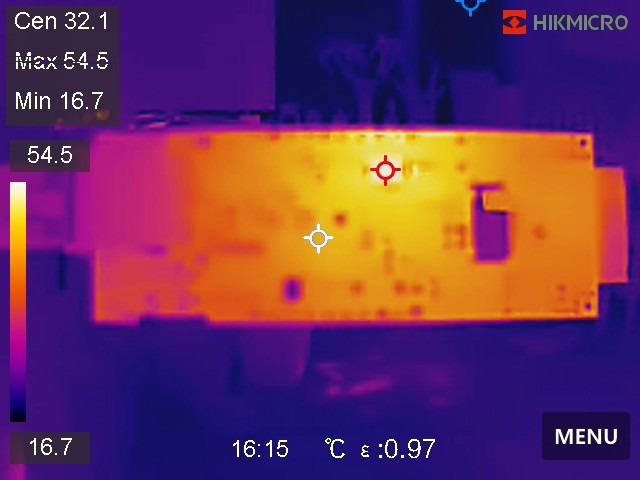
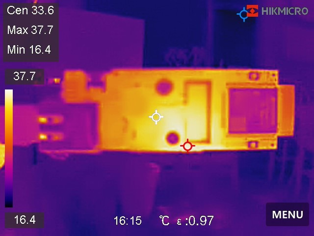
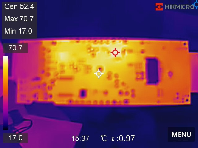
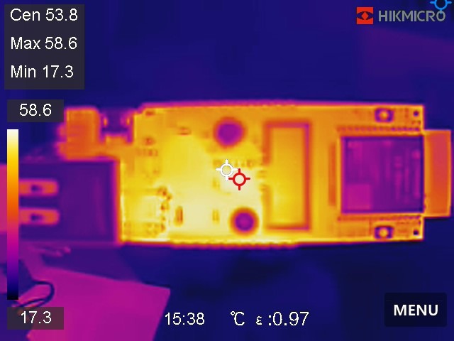
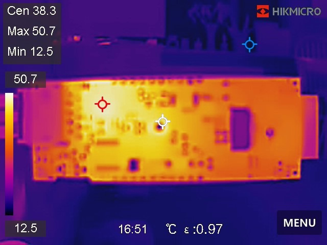
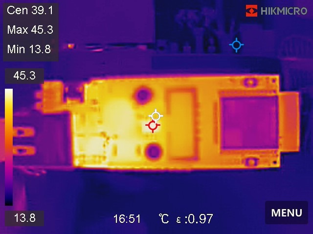
To be honest, I was a little shocked at how high both the thermal heating and the PoE power consumption is. I had been assuming ~1 watt for an empty board off PoE. I was out by 50%, which adds up if you fit lots of boards. Add some peripherals – in this case, 2x 5v <=> 3.3v level shifters, a BME280 temperature, humidity and pressure sensor, and the rotary encoder on the GA12-N20 motor – and you’re burning ~1.75 watts per board. If I fit thirty of these boards, that’s 52 watts of heat being pumped into the house. To put that into context, my entire 3000 litre thermal store in summer leaks ~60 watts into the house. Adding another fifty watts of background heating puts into jeopardy no overheating of this house in summer!
Removing resistor R42 which burns 500 mW to keep the PoE supply going is an obvious step, but I think we can do better than 1.2 watts idling with that resistor removed for not much extra money. PoE doesn’t actually require a constant 500 mW of load to stay active – rather it needs to see 500 mW of load for at least 60 milliseconds every 340 milliseconds. This is a duty cycle of 15% on a tick of 400 milliseconds, reducing amortised load to keep PoE active to 75 mW. If I could get these boards mostly into deep sleep, and have some sort of pulse generator generate load at the right duty cycle, that could reduce heat contributed to the house significantly.
My first instinct was a 555 pulse timer circuit which are cheap and plentiful at €0.58 inc VAT delivered each, however it turns out when they’re off they consume ~425 mW which seems like we could do better. After quite a bit of research I landed on a surprising conclusion: the most cost effective way of implementing a low power pulse generator is actually a second ESP32 chip which does nothing but deep sleep for 340 ms and power on for 60 ms. This seems wasteful for a microcontroller as powerful as an Intel Pentium II from 1997, but the economics are what they are – I can get an ESP32-C3 on a breakout board with USB-C, onboard programmer and 3.3v buck converter delivered for €1.50 inc VAT! Madness! And it doubles as ‘the load’ because you can turn on the Bluetooth and Wifi stacks to consume up to 200 mW @ 3.3v (which should be just enough to consume 500 mW @ PoE), whereas the 555 circuit would need an additional load resistor and wiring. Assuming that the 2 mW deep sleep is the same for both, and conversion losses might be 5x at such a low current, it might draw 25 mW from PoE during the off cycle. That should bring total PoE draw to under 100 mW per device amortised, so under three watts for the total. Which is better than 52 watts!
In case you’re wondering why not use the existing ESP32 for this, one could theoretically modify ESPHome to do this for you. However, it would be a lot of work – the ESP32 has a bootloader stage and a main stage, and it takes 100 milliseconds to reach the main stage. So to get the timings we need, the firmware must exclusively operate within the bootloader stage. That’s deep customisation of ESPHome, and to be honest for €1.50 I can make the problem go away so a second ESP32 it is.
The ESP32-C3 boards are on their way from Aliexpress and when they arrive they surely will be written about here. Watch this space!
If I were starting all this again – and it wasn’t obvious at all at the beginning nor was it available until recently – Olimex now have a v2 of the ESP32-POE which can draw 25 watts instead of 12.5 watts from PoE, and has a built-in 12v 1.5 amp supply. That bilge fan if running off 12v should consume less than that though it would need a slow start implementing to prevent brown out. I’ve already bought the PoE switches etc and they were all sized for max 12.5 watts per port, so that ship has sailed. Still, if you’re reading this thinking about replicating what I’ve done, it’s worth bearing in mind.
Next post I might – or might not – cover the blind automation or the LED strips or the ESP32-C3 boards. We shall see how things go. I kinda do want a video of a real blind going upwards and downwards on command and demonstrating that when it gets to the top, it stops on its own. I have some 3D printing between now and then to reach that, not least because my initial 3D print of the blind spool ended up losing its grip on the motor because the motor’s torque is so strong and its burred the plastic, despite that being ABS. So I had to go get little metal cogs for the end of the motor and I’ll need to redesign the blind spool to fit the metal cog.
Still, what else do I have to be doing? At least this advances the house build in its own way.
| Go to previous entry | Go to next entry | Go back to the archive index | Go back to the latest entries |