My remaining prototype projects are:
3D printing extensions to an IKEA Fridans blind to avoid the expense of IKEA Fytur blinds.
Dimming RGBW LED strips with my ‘new’ IRF540N MOSFET boards.
Figure out a solution to reducing the power consumption of my cheap ESP32-POE boards.
I’m pretty much done with all three. The blinds have taken the most effort and have been the most frustrating, but I have a video of them in operation and I just need to write it all up. I’ve also completed the other two in full and those are what I’ll be talking about in this post.
One these prototypes are complete, my next goal is to draw into a 3D representation of the house where all the wiring and items will go in detail. I already have done a full set of schematic wiring diagrams, but it would save time onsite if I knew exactly what wire goes where and it may help me save money on wire by optimising routing. So I’ll still be busy doing house build aiding work.
Throwing a whole PC at a pulse generator
Last post I mentioned:
After quite a bit of research I landed on a surprising conclusion: the most cost effective way of implementing a low power pulse generator is actually a second ESP32 chip which does nothing but deep sleep for 340 ms and power on for 60 ms. This seems wasteful for a microcontroller as powerful as an Intel Pentium II from 1997, but the economics are what they are – I can get an ESP32-C3 on a breakout board with USB-C, onboard programmer and 3.3v buck converter delivered for €1.50 inc VAT! Madness! And it doubles as ‘the load’ because you can turn on the Bluetooth and Wifi stacks to consume up to 200 mW @ 3.3v (which should be just enough to consume 500 mW @ PoE), whereas the 555 circuit would need an additional load resistor and wiring.
Those ESP32-C3 “Super Mini” boards arrived from Aliexpress a week ago. According to https://roryhay.es/blog/esp32-c3-super-mini-flaw, mine are the flawed design which puts the Wifi antenna (the red thing on the left) too close to the external 40 Mhz clock (the silver component top left) which impacts reception quite badly:
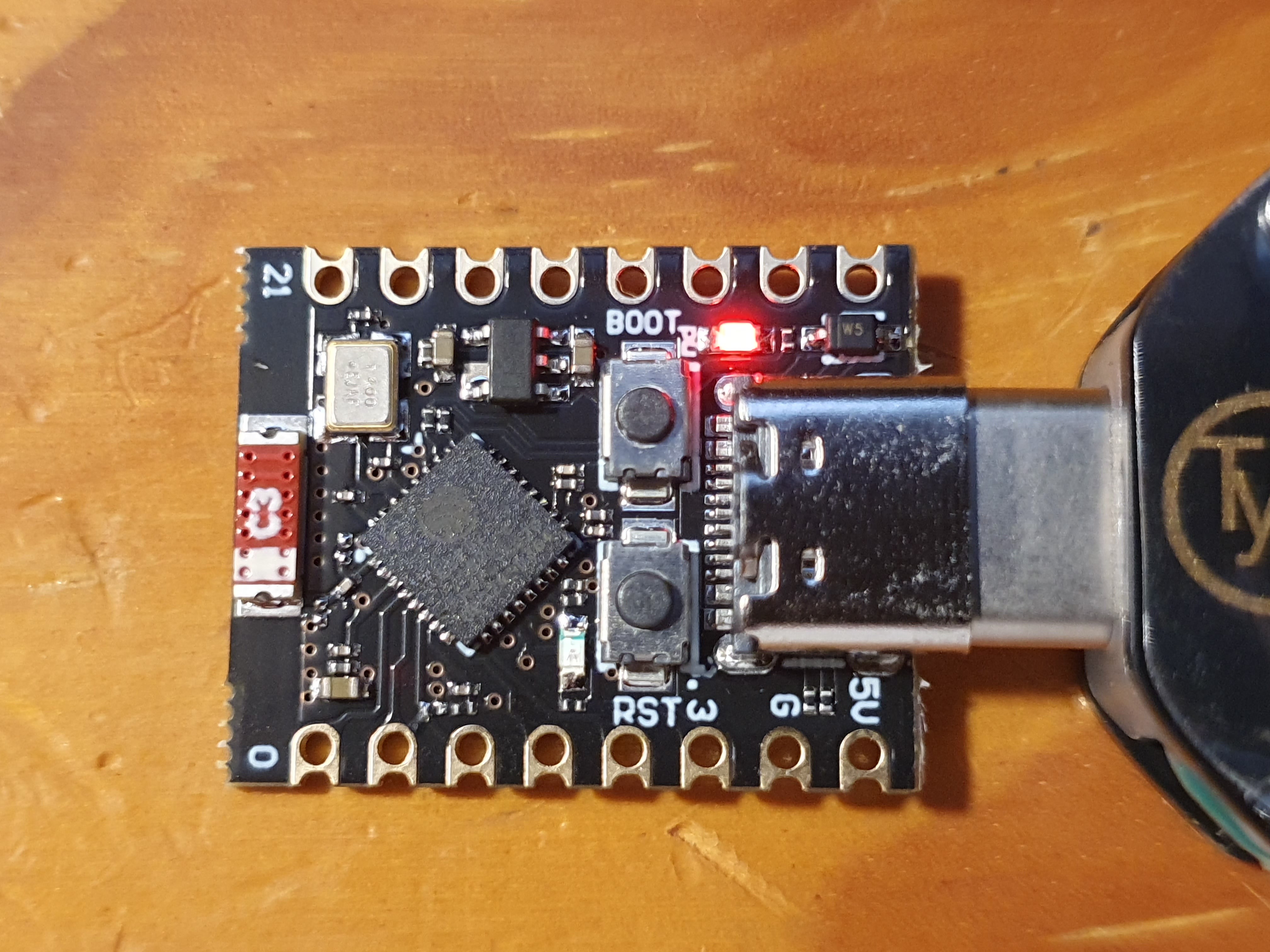
I never found the Wifi on the Olimex ESP32 board of much use, it has a much better embedded antenna design which I still find nearly useless, especially as it is 2.4Ghz and even a few of these devices in a room quickly overwhelms that spectrum such that it denigrates into unreliable noise. I certainly never would have any use for the Wifi with an even worse embedded antenna, so I don’t care that this is the flawed design for Wifi. Especially for €1.50 inc VAT. These boards do have the ESP32-C3 with the embedded 4Mb flash (amazingly, some do not), and it is the latest ESP32-C3-FH4 revision whereas some boards ship with a retired earlier revision. Build assembly, as you can see, isn’t the cleanest but I’ve also seen a lot worse. I will say that when I asked it to list Wifi APs it could see, it found an identical list to my phone and the signal strengths it reported were only a bit worse, but I didn’t try connecting to any as I won’t ever need that functionality.
Here are the pinouts:
In addition to your twelve very flexible i/o, the ESP32-C3 has 400 Kb of RAM, 4Mb of flash, it runs at up to 160 Mhz and has a 32 bit RISC-V instruction set. It is only single cored so if you do run a Wifi or BLE stack, that will consume a lot of CPU wherea the Xtensa ESP32s throw a whole CPU core at Wifi and BLE and leave the other core entirely for you. It is also missing hardware floating point, but does have hardware crypto acceleration.
For €1.50 inc VAT delivered, that is a whole load of computing for the money. This is a very capable dev board for the money. It’s almost embarrasing the value here.
You can, however, actually get still cheaper on a breakout board with USB connected flash programmer and a 5v to 3.3v buck converter. Yes, even less cost than €1.50 inc VAT delivered:
- A clone of the Waveshare RP2040-Zero dev board for €1.29 inc VAT delivered. This is the same RP2040 microcontroller of Raspberry Pi fame, and the board is generous with nineteen i/o on pins and a further nine i/o if your micro soldering skills are good. It also has a single onboard WS2812 RGB LED if you fancy a very small light show.
- A clone of the ATTiny85 dev board for €0.93 inc VAT delivered. This is an eight bit CPU compatible with Arduino, and it has six i/o pins.
(I deliberately omit the fake STM32 clones which are well known to be sufficiently flaky and weird that they aren’t worth the hassle at this price point. The RP2040 chip on these boards is genuine, as is the ATTiny85, it’s just the dev board which is a clone of a branded (and much more expensive) board. As the chip is genuine and not a bad attempt at a reproduction, you get consistent behaviour and the toolchains will work without issues)
Of those two, the RP2040-Zero looked worth a speculative purchase, and the Aliexpress vendor with both the ESP32-C3 Super Mini boards and the RP2040-Zero boards gave you free shipping if the order was over €37. So, I ordered this bag of both MCU types, mostly the ESP32-C3 with a few of the RP2040-Zero’s thrown in:
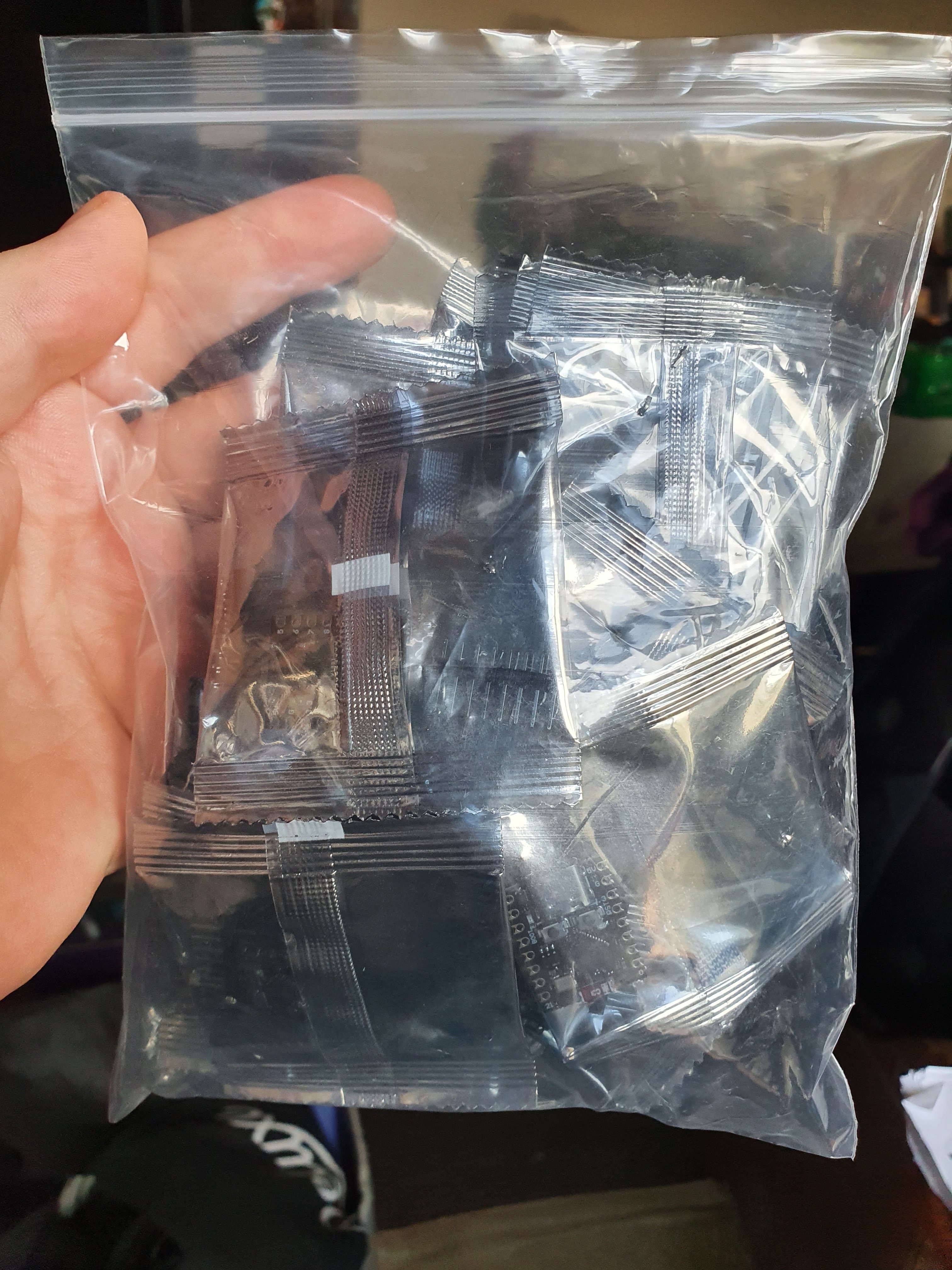
I still can’t quite believe that in 2024 I can buy two dozen 1997 era PCs in a bag for under €40 inc VAT delivered. Madness!
The RP2040-Zero boards have more i/o than the ESP32-C3, and have the whole Raspberry Pi ecosystem with them, but otherwise are inferior in almost every way. They have nearly half the RAM, half the flash, slower clock speed and they in fact run far slower again than any ESP32. There is obviously no Wifi nor Bluetooth. For €0.20 inc VAT saved they probably aren’t worth it except for the Raspberry Pi ecosystem and they were also a guarantee that if the ESP32-C3 boards didn’t work out, I’d have a fallback. I’m glad to report that the ESP32-C3 boards did work out, so those RP2040’s are probably going to gather dust until a use case for them turns up.
One of those use cases might be as a MicroPython learning platform. My son occasionally types in Python Turtle programs to a laptop. He doesn’t understand enough to write his own programs yet, but if he sticks with it and gets good enough that he can, certainly one of those RP2040 is ideal for learning. Once you flash MicroPython onto it, you literally plug it in to a PC, connect to the serial port it exposes and voila, you’re in a Python interpreter. You can flash LEDs, poke pins, there is actually a fair fist at an embedded debugger on there. This is stuff Raspberry Pi does well, and to date they’ve had superb support for ancient hardware so I expect latest firmwares will be available for those boards a decade or more from now. And hey, if you just want a quick and dirty MCU try out of something embedded from within an interactive interpreter, that’s more hassle with an ESP32 to set up than a RP2040.
Completing Olimex ESP32-PoE detailed power consumption
Last post I reported disappointing power consumption measurements for the Olimex ESP32-PoE board when powered from PoE, and I speculated that a pulse generator using these cheap ESP32-C3 boards would produce a superior result:
Removing resistor R42 which burns 500 mW to keep the PoE supply going is an obvious step, but I think we can do better than 1.2 watts idling with that resistor removed for not much extra money. PoE doesn’t actually require a constant 500 mW of load to stay active – rather it needs to see 500 mW of load for at least 60 milliseconds every 340 milliseconds. This is a duty cycle of 15% on a tick of 400 milliseconds, reducing amortised load to keep PoE active to 75 mW. If I could get these boards mostly into deep sleep, and have some sort of pulse generator generate load at the right duty cycle, that could reduce heat contributed to the house significantly … Assuming that the 2 mW deep sleep is the same for both, and conversion losses might be 5x at such a low current, it might draw 25 mW from PoE during the off cycle. That should bring total PoE draw to under 100 mW per device amortised, so under three watts for the total.
I can tell you now I didn’t get the power consumption that low as there are inefficiencies in the chain. But I can complete the table now:
| USB (5.2v) | PoE (52.6v) unmodified | PoE (52.6v) with R42 resistor removed | |
|---|---|---|---|
| Deep sleep (two LEDs shining) | 2 mW | 579 mW | switch cuts power, so must be < 500 mW |
| Idle in ESPHome no ethernet (two LEDs shining) | 386 mW | n/a | n/a |
| As above with ESPHome trying to get ethernet | 454 mW | n/a | n/a |
| Idle in ESPHome with ethernet (four LEDs shining) | 553 mW | 1525 mW | 947 mW |
| Idle as above with all peripherals for a bedroom | 600 mW | 1736 mW | 1158 mW (estimated) |
| Deep sleep + ESP32-C3 pulse generator to keep PoE alive (three LEDs shining plus one pulsing) | 46 mW | 170 mW |
So about twice worse than originally hoped for, most of which I would guess is inefficiency in the buck converters at very low currents. But still a lot better than any of the other alternatives above, so I think we’ll take it.
Here is it in action, I turn on the blue LED when the board is burning power and off when it goes into deep sleep:
ESP32-C3 Super Mini based pulse generator keeping PoE going during main board deep sleep
And, for reference, here is the snippet of ESP-IDF code which I wrote:
#define US_DEEPSLEEP (400000 - US_BURN)
#define US_BURN (66000) // 60000 plus min 5200 for period before wifi enable

void app_main(void)
{
    esp_sleep_wakeup_cause_t wakeup_cause = esp_sleep_get_wakeup_cause();
    int64_t since_boot = esp_timer_get_time();

    // Turn on the LED to burn a few extra mW
    gpio_reset_pin(8);
    gpio_set_direction(8, GPIO_MODE_OUTPUT);
    gpio_set_level(8, 0);

    // Initialize NVS. Apparently required for Wifi.
    esp_err_t ret = nvs_flash_init();
    if (ret == ESP_ERR_NVS_NO_FREE_PAGES || ret == ESP_ERR_NVS_NEW_VERSION_FOUND)
    {
        ESP_ERROR_CHECK(nvs_flash_erase());
        ret = nvs_flash_init();
    }
    ESP_ERROR_CHECK(ret);

    // Fire up wifi to add an extra ~400 mW power consumption
    int64_t before_scan = esp_timer_get_time();
    ESP_ERROR_CHECK(esp_netif_init());
    ESP_ERROR_CHECK(esp_event_loop_create_default());
    esp_netif_t *sta_netif = esp_netif_create_default_wifi_sta();
    assert(sta_netif);
    wifi_init_config_t cfg = WIFI_INIT_CONFIG_DEFAULT();
    ESP_ERROR_CHECK(esp_wifi_init(&cfg));
    ESP_ERROR_CHECK(esp_wifi_set_mode(WIFI_MODE_STA));
    ESP_ERROR_CHECK(esp_wifi_start());
    esp_wifi_scan_start(NULL, false);

    // Spin loop the CPU to burn another ~25 mW
    while (esp_timer_get_time() < US_BURN)
    {
        // vTaskDelay(10);
    }

    int64_t after_scan = esp_timer_get_time();
    printf("\nsince boot = %lld us\n", since_boot);
    printf("wakeup cause = %d\n", (int)wakeup_cause);
    printf("before wifi scan = %lld us\n", before_scan);
    printf("after wifi scan = %lld us\n", after_scan);
    int64_t before_sleep = esp_timer_get_time();
    printf("before deep sleep = %lld us\n", before_sleep);
    esp_deep_sleep(US_DEEPSLEEP);
}
I measured this burning 450 mW at peak with my USB power meter and 3 mW during deep sleep. The code which initialises non-volatile storage takes quite a bit, about three milliseconds and it takes two milliseconds to boot. This is why we burn for 66 milliseconds instead of 60 milliseconds to account for the period before burn begins.
I threw the above together with a few hours of work. I was impressed with the ESP-IDF framework, it is very well documented and the APIs are complete and well designed in the bits I looked at. The toolchain has a Visual Studio Code extension that ‘just works’ on Windows, Linux or Mac OS, and it’s full fat C++ 17 as it’s based on the current latest stable GCC 14.
There is an awful lot to like here I must admit. Compared to embedded systems development at this price point even five years ago … exponential improvement remains live and well at this price point. I can see future ESP32 class MCUs on a dev board with USB based flash programmer coming in well below one euro soon enough. Madness!
Dimming RGBW LED strips with my ‘new’ IRF540N MOSFET boards
Last August I wrote:
Many moons ago after testing IRF520N MOSFET based solutions for dimming LED strips, I realise that I had bought poorly and I should have bought IRF540N MOSFETs instead as they should run much cooler. Easily two years ago now I did buy a bunch of four channel IRF540N MOSFET boards, but I’ve never tested them in action. I’d like to get that done, to create peace of mind that this solution will definitely work if asked and they do run cool as the maths had predicted.
This one was a bit bad, I had had that IRF540N board since January 2023. To be honest, I was sufficiently sure it would be fine it wasn’t high priority but as I run down the prototypes to work on, this was an easy one to also clear off the deck.
Back in 2021 when I first started testing prototypes – yes, three years ago now – I put in a prototype cove lighting operated by a Devantech industrial PIC32 board. It used an IRF520N MOSFET to do the dimming, and boy did it get hot with perhaps 2 amps going through it. This is due to maths, here are my estimates from their datasheets of waste heat generation for a control voltage of 10v and the MOSFET’s temperature is 20 C (they leak more heat as they get hotter):
| Current | IRF520N watts | IRF520N temp | IRF540N watts | IRF540N temp |
|---|---|---|---|---|
| 0.63 A | 0.08 W | +5.0 C | 0.02 W | +1.3 C |
| 1.00 A | 0.20 W | +12 C | 0.05 W | +3.2 C |
| 2.00 A | 0.80 W | +50 C | 0.2 W | +13 C |
| 2.50 A | 1.25 W | +78 C (needs cooling) | 0.33 W | +20 C |
| 4.00 A | 3.20 W | +198 C (needs cooling) | 0.82 W | +52 C |
Most MOSFET boards of any kind put a LED in series with the control signal which removes 0.5v, so with a level shifter you end up with a control voltage of about 4.5v after the LED. This is obviously a good bit lower than the 10v most MOSFET datasheets describe, which can result in even more heating than the above as more current will leak due to the weaker clamp.
This particular IRF540N board happens to be wired differently from usual however. To be honest, I knew that when I did the research and I bought it two years, but I had forgotten since and so this testing and wiring is wrong as you’ll shortly see.
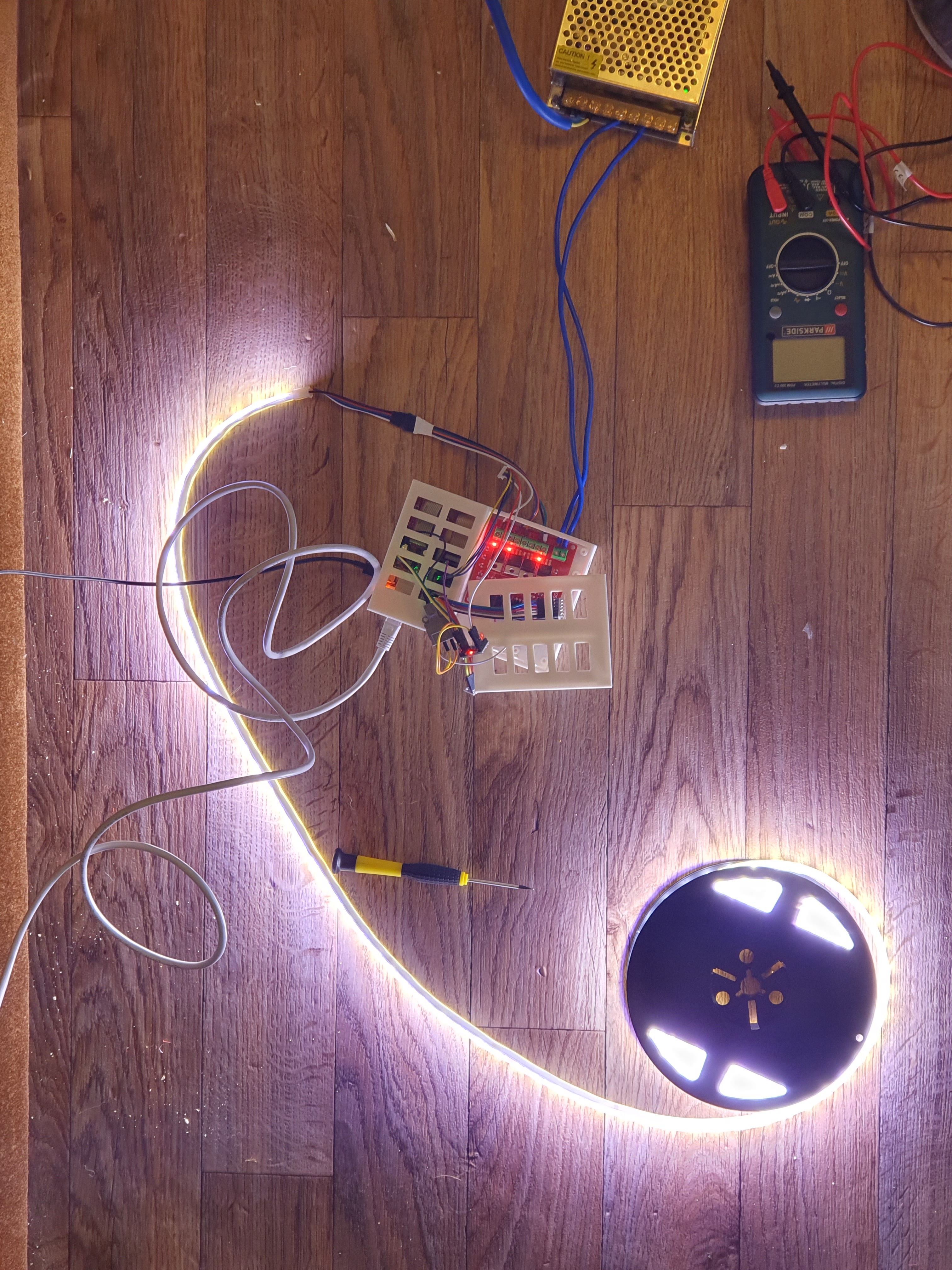
ESPHome controlling the RGBWW LED strip
There isn’t much to the automation side of things here – ESPHome knows about four channel RGBWW LED strips, and here it applies a 15 kHz PWM to each channel which is more than flicker free. In case you’re wondering why the green stays on, more on that shortly.
To test heating, I left them on 100% for a period. These are my outdoor LED strips for the house soffit and I reckon they consume about 72 watts mainly clamped by the overly thin anode wire which probably pegs current to 3 amps or so. When I fit these to the house, I’ll be running a second anode wire to the other end just to reduce heat wastage.
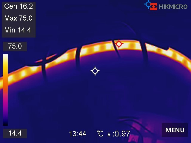
You can clearly see the hot anode wire standing out – why these Chinese RGBWW LED strip manufacturers insist on fitting identical gauge wire for the common anode I just do not understand. I can’t believe it actually saves much money, maybe a few cents, but it would make far more sense electrically speaking to either fit a slightly thicker wire, or even just double up on the wires.
The strip itself gets up to 75 C, but as these will be living outside up high where there is a breeze I am not worried about them warping the soffit plastic or anything (I also have them standing off slightly using clips). Also, the extra anode line will help a bit I think by not turning the common anode into a heating element.
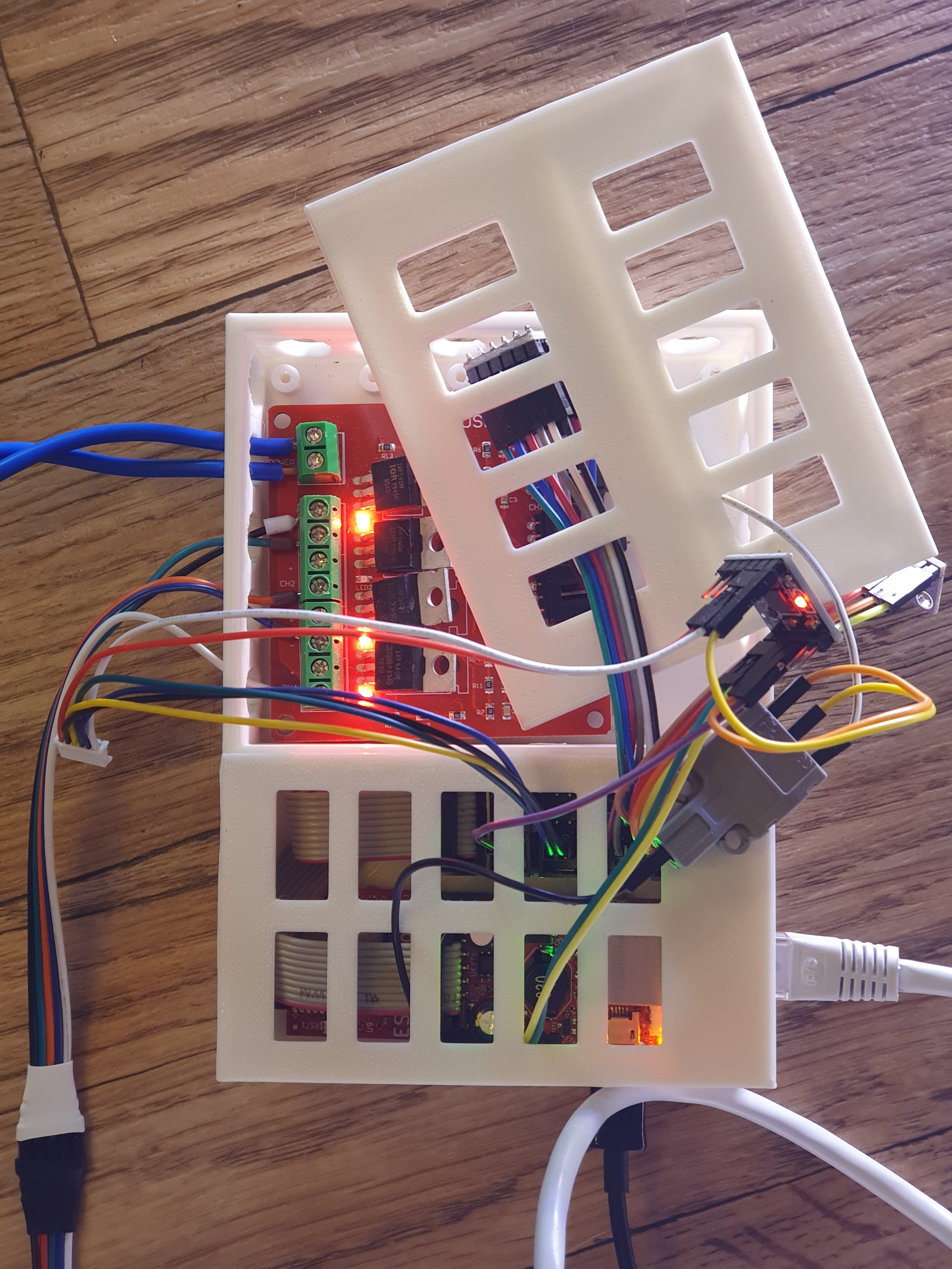
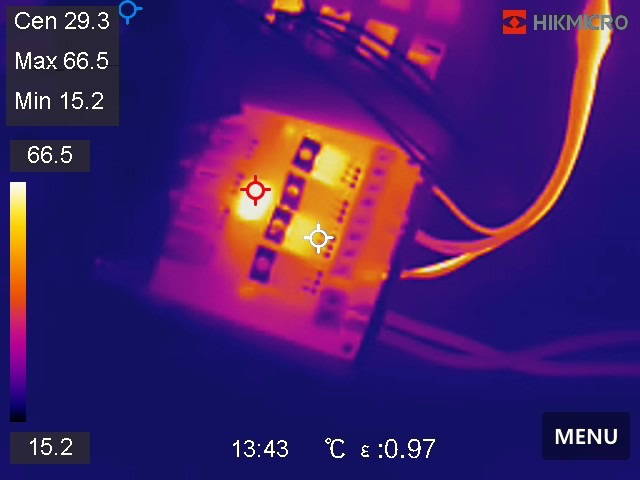
The ‘MOSFET4 U04’ board which costs about €2 inc VAT delivered shows very little heating by the MOSFETs, maybe +15 C. What is surprising is that the PS2801-4 optocoupler chip gets rather warm, though it remains well inside its datasheet temperature range. There was no PWM as it is fully on, so it’s not rapid switching causing the heating. Its datasheet says it’s happy with 3.3v signalling and it’ll switch outputs of up to 80v.
The heating made me look a bit more into the circuit, which then made me realise that I had wired it wrong by using a 5v level shifter. The optocoupler is powered by the MOSFET power NOT Vin as would be normal in MOSFET breakout boards, so the Vin is completely ignored and the optocoupler detects only the difference between signal and ground. There is a voltage divider for the input which divides the MOSFET voltage by approximately 2.5 to create the input signal for the IRF540N. The MOSFET has a maximum signal voltage of 20v, so the maximum safe voltage for the load is 50v. I’m using 24v for the LED strip, so that yields a 9.6v signal voltage. This is a clever design – it means my 3.3v to 5v level shifter is completely unnecessary, and indeed may be driving too much current through the optocoupler making it get hot. That inspired me to rewire and retest this by removing the level shifter, and this was the result:
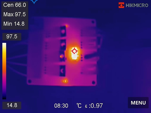
Well that is a surprise! This is now the optocoupler driven directly from the ESP32 3.3v output rather than level shifted 5v. What you’d expect is the lower voltage and surely much lower max current would produce less heating, but for some reason it appears to have the opposite effect. I didn’t connect the load in this case, but assuming it wouldn’t cause voltage drop I can’t see any reason why that would affect the heating of the optocoupler.
Looking again at the PS2801-4 optocoupler datasheet, apparently it’ll dissipate up to 200 mW of heat per channel. Four channels is one watt. That might explain things, it is a small chip. I think it’ll need a heatsink when deployed. Good to learn!
Finally, there is a question about why the green is always on? A thermal photo with all signals low explains everything:
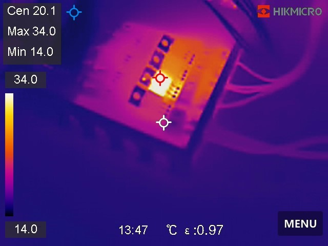
That’s clearly a busted MOSFET or it isn’t wired in correctly – either way, it’s always on. I note that the optocoupler is now cool, so I suspect the fault isn’t there, but it can be hard to say. In any case, for €2 inc VAT you just grab another board, and I bought a bag of them.
Northern Lights
About six months ago I was very fortunate to see the Northern Lights come as far south as Cork. We are currently in a solar maximum, I thought I’d give a quick peek assuming it would be clouded out. It was not – once my eyes adapted, I got twenty minutes of reds, greens and blues strobing, pulsing and twisting above me easily visible with the naked eye. Then the clouds came in, so it was over. I didn’t bring my phone with me at the time thinking I wouldn’t see anything, and I could see the clouds coming so I didn’t want to ruin my night adapted vision by getting my phone. So I captured no photos.
I honestly thought that would be the one and only time I’d ever see Northern Lights this far south in my life. However, a coronal mass ejection hit the planet a few days ago, and most unusually it was a clear night. As this was an ejection, the lights were concentrated to the north rather than extending below Ireland like last time, and unfortunately Mallow town is to my north so light pollution rather ruined the view. I did get this:
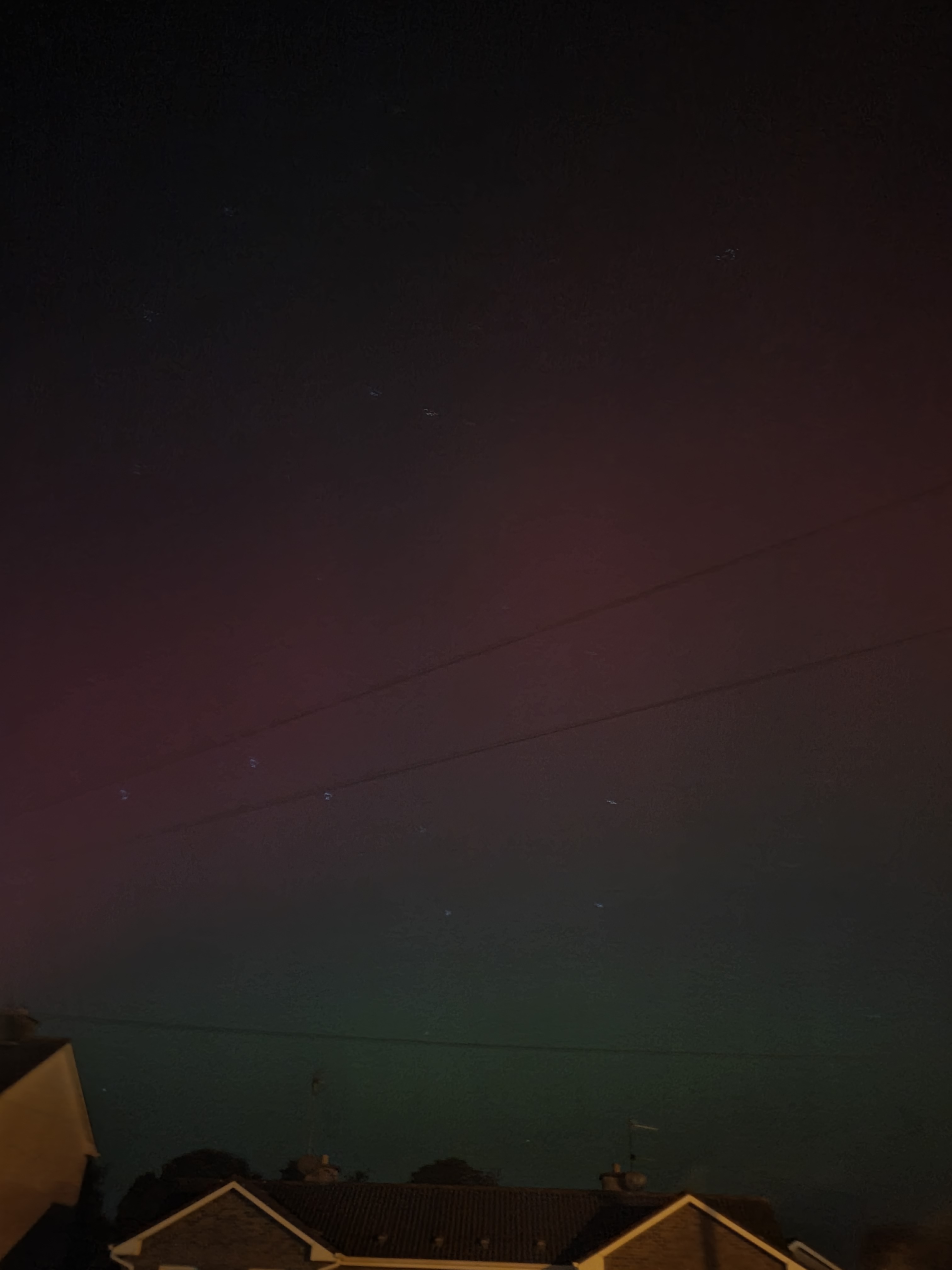
And that’s very similar to what you could see with the naked eye. You could see the colours just fine, despite the street lamps immediately around and Mallow town spraying light all over it.
Contrast that with the site for my future house which is on the edge of a dark sky reserve:
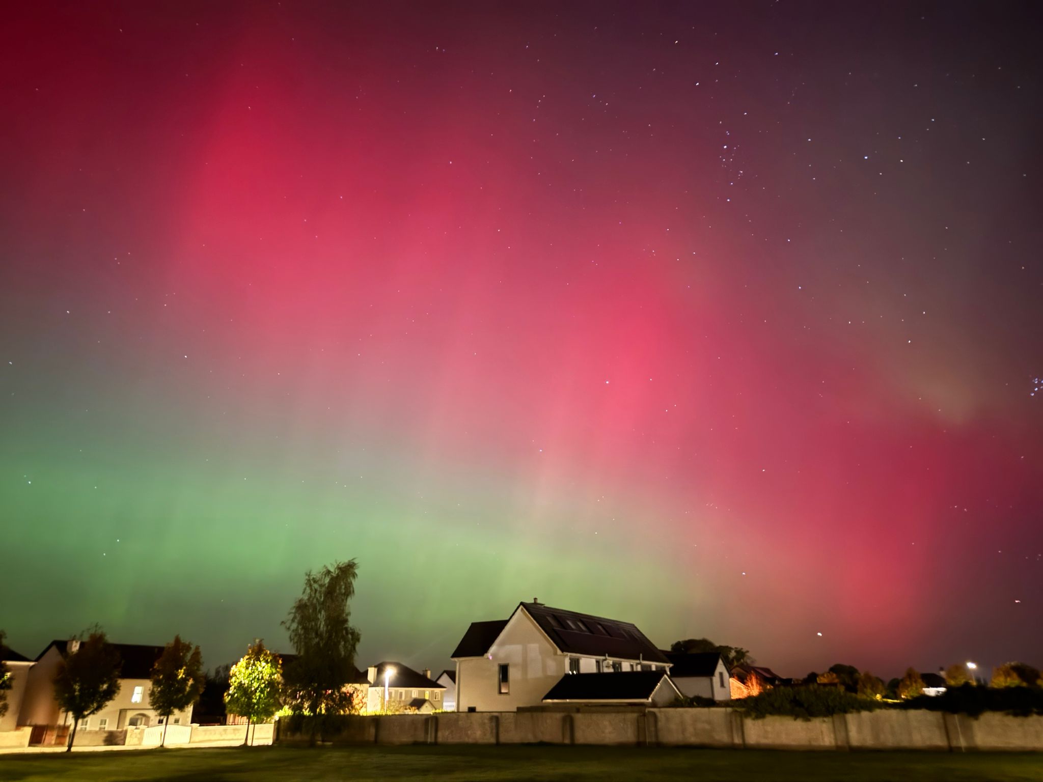
This was taken at almost the same time by my neighbour Rob with his iPhone. Without doubt Apple have done some postprocessing there, so it wasn’t quite that nice with the naked eye. But it should have been a lot better if you let your eyes adapt than what was possible where I live with all those bright street nights to the north of my house preventing you adapting.
So there you have it – I’ve seen the Northern Lights twice in my life now! And they were awesome.
| Go to previous entry | Go to next entry | Go back to the archive index | Go back to the latest entries |